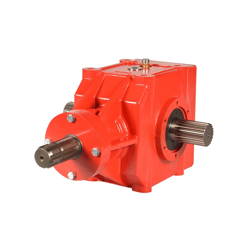
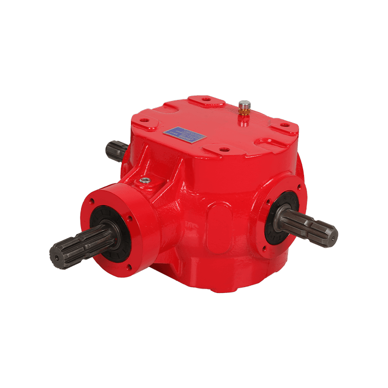
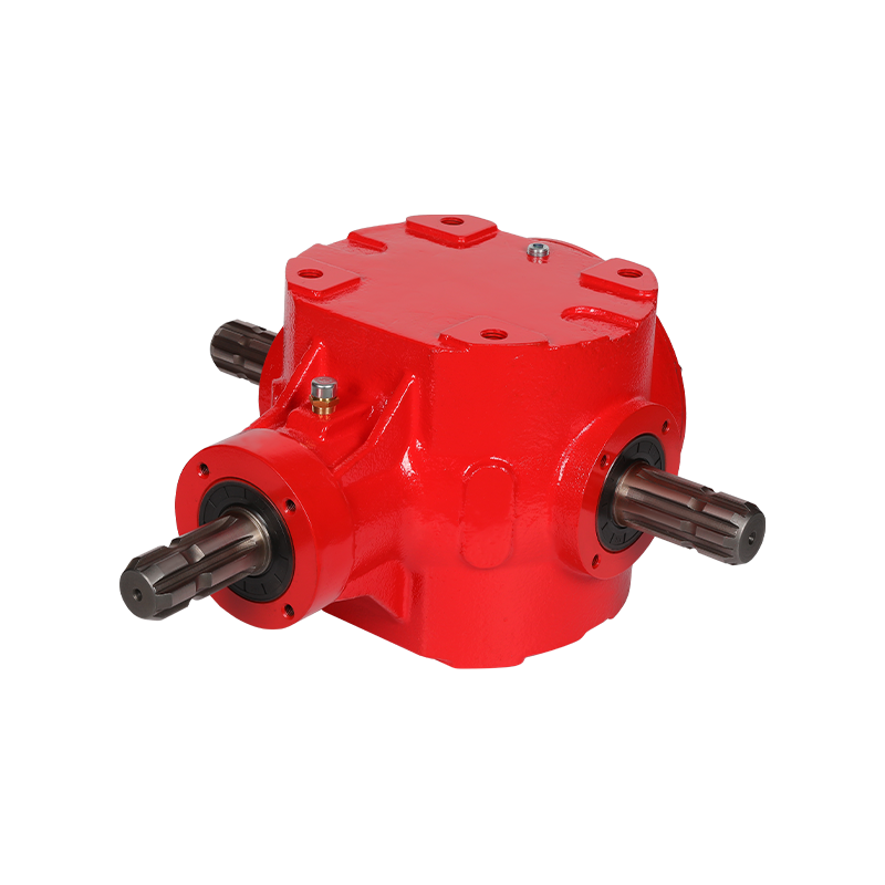
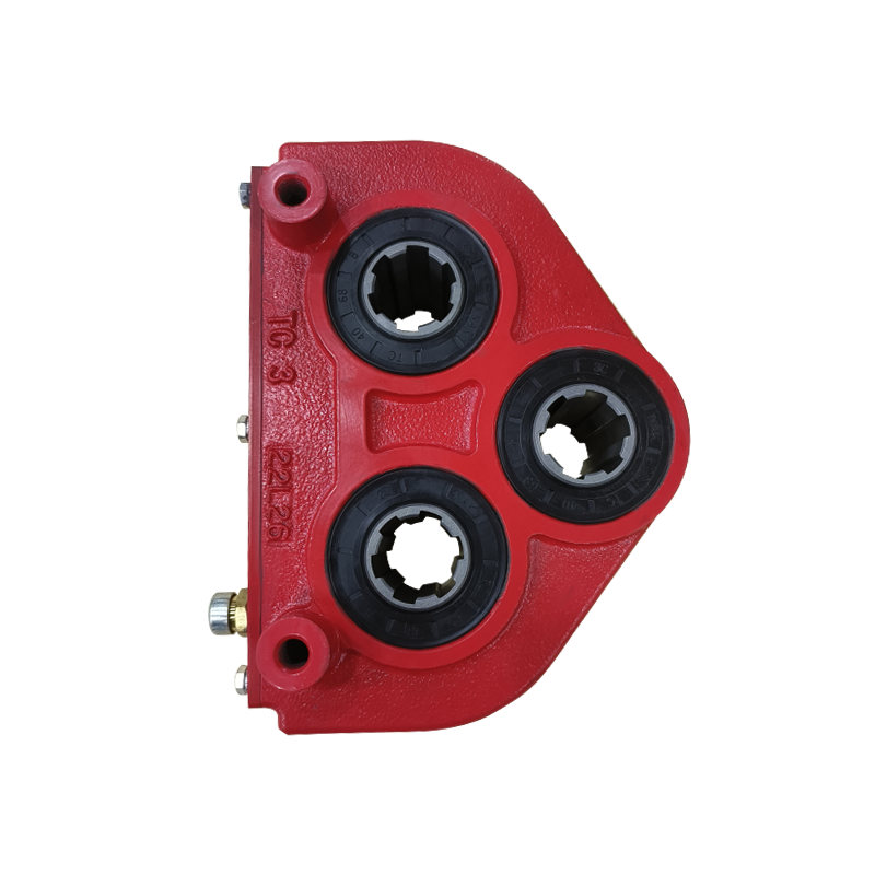
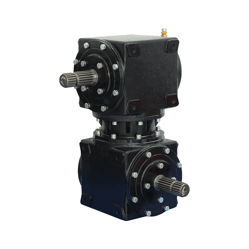
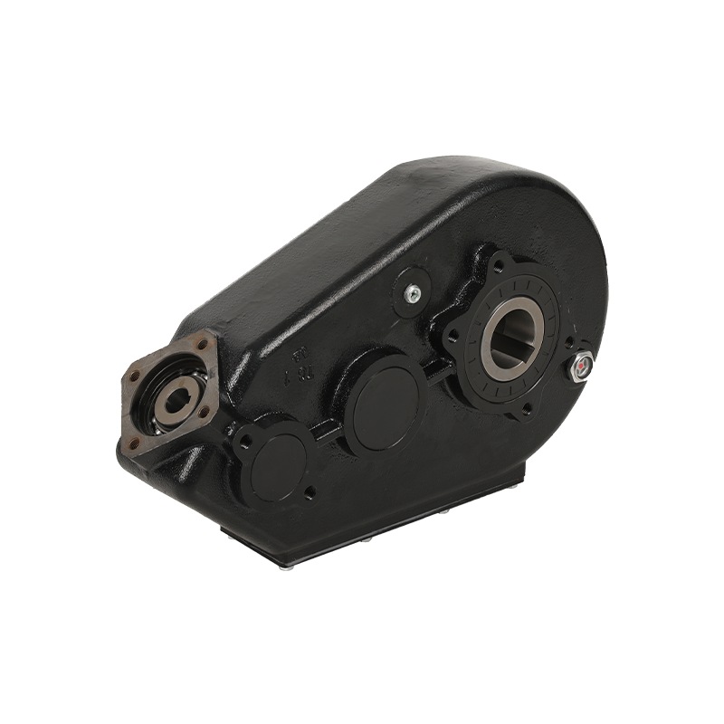
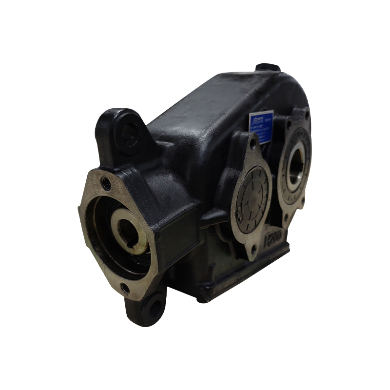
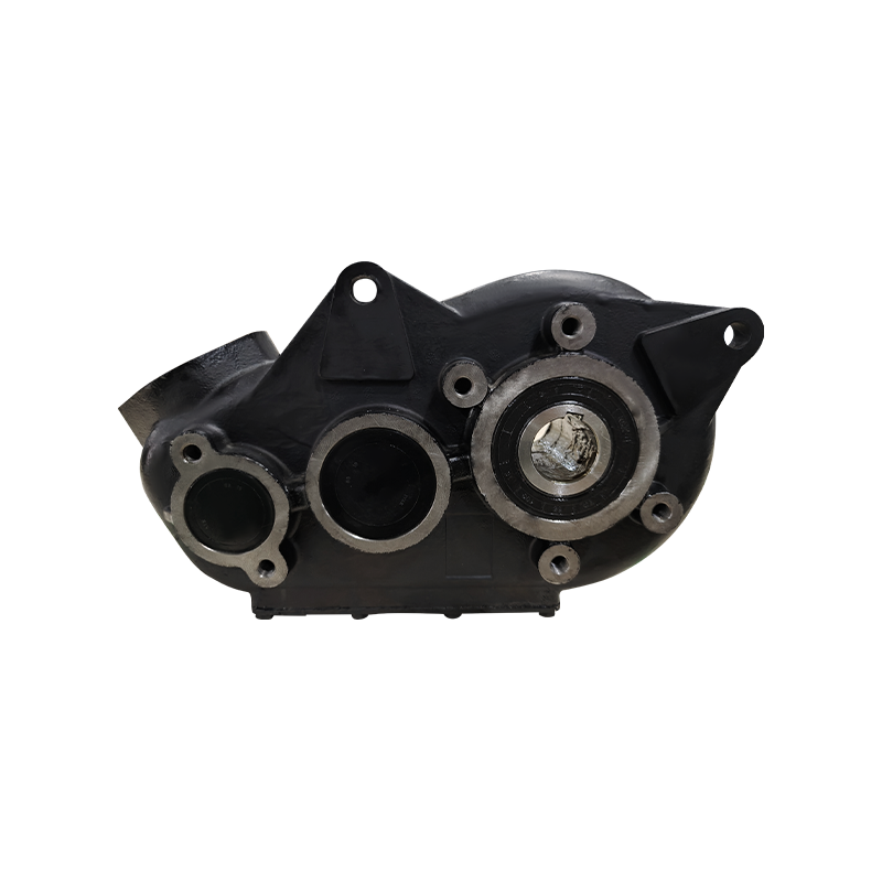
In the world of machinery, from the humble washing machine to the powerful conveyor drives in a factory, there exists a ubiquitous workhorse: the universal gearbox. Its core function is deceptively simple yet fundamentally critical—to serve as an intermediary between a power source (like an electric motor) and a load, ensuring that the motor runs efficiently while the task gets done effectively.
The Fundamental Trade-Off: Understanding Torque and Speed
Before diving into the gearbox itself, one must grasp the immutable relationship between torque and rotational speed. In simple terms:
Speed (RPM): The number of rotations the output shaft makes per minute. High speed means something is spinning fast.
Torque: A twisting force that causes rotation. Think of it as the “muscle” or “pulling power.” High torque is needed to start a heavy load moving, lift a weight, or crush a material.
The relationship is governed by the Law of Conservation of Energy. Energy (or power, which is energy over time) cannot be created or destroyed, only converted. In a perfectly efficient system:
Power In ≈ Power Out
Since mechanical power is calculated as Torque (τ) × Rotational Speed (ω), the equation becomes:
(Torque_in × Speed_in) ≈ (Torque_out × Speed_out)
This reveals the core principle: For a constant input power, torque and speed are inversely proportional. You cannot increase both simultaneously from a fixed power source. A gearbox is the tool that allows you to choose the balance between them.
To Increase Torque: You must decrease the output speed.
To Increase Speed: You must decrease the output torque.
A universal gearbox is essentially a “torque-speed converter,” allowing a motor to operate at its optimal, efficient RPM while providing the high-torque, low-speed force required by the load.
The Core Components: How Gears Create Mechanical Advantage
A gearbox achieves this conversion through a system of gears. The three key components involved are:
Input Shaft: Connected directly to the motor, receiving power at the motor’s speed and torque.
Gears of Various Sizes: These are the heart of the system. Gears are toothed wheels that mesh together to transmit power and motion.
Output Shaft: Connected to the load (e.g., a wheel, a mixer, a conveyor belt), delivering the modified speed and torque.
The mechanical advantage comes from the difference in the number of teeth on the meshing gears. This difference is known as the Gear Ratio.
The Magic of the Gear Ratio
The gear ratio is the fundamental calculation that dictates the gearbox’s behavior. It is defined as:
Gear Ratio = Number of Teeth on Driven Gear / Number of Teeth on Driving Gear
It can also be calculated using the input and output speeds:
Gear Ratio = Input Speed (RPM) / Output Speed (RPM)
Let’s examine the two primary scenarios:
Scenario 1: Speed Reduction for Torque Multiplication (The Most Common Case)
This is what happens when a small gear (the “driving” or “input” gear) drives a larger gear (the “driven” or “output” gear).
Action: The small input gear rotates quickly but with relatively low torque. For every full rotation it makes, it only engages and turns the larger gear a fraction of a turn.
Result: The output speed is reduced. However, because the larger gear has more teeth, the force is distributed over a greater radius, resulting in a significant increase in output torque.
Real-World Analogy: Think of a bicycle in its lowest gear. You pedal many times (high input speed) to make the rear wheel turn just a few times (low output speed). This allows you to apply massive torque to the pedals to climb a steep hill.
Scenario 2: Speed Increase for Torque Reduction
This is the reverse, where a large gear drives a smaller gear.
Action: The large input gear rotates slowly. For every full rotation, it pushes the smaller gear through multiple rotations.
Result: The output speed is increased, but the output torque is decreased.
Real-World Analogy: This is like a bicycle in its highest gear. One pedal stroke (low input speed) makes the rear wheel spin many times (high output speed), perfect for flat, high-speed cruising where less torque is needed.
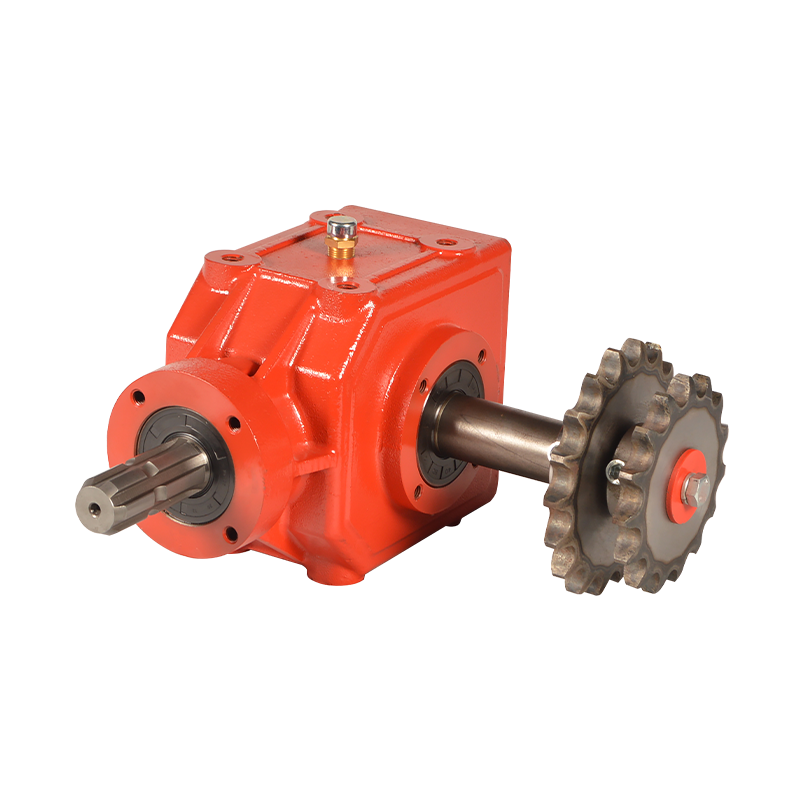
Types of Universal Gearboxes and Their Adjustment Mechanisms
The term “universal” implies adaptability. Different gearbox designs achieve this adaptability in different ways to suit various applications.
1. Stepped-Ratio Gearboxes (Manual Transmission)
How it Works: This type contains multiple sets of gears with fixed, pre-determined ratios. The operator (or an automated system) physically shifts between these sets.
Adjusting for Load: To handle a changing load, you select a different gear. Starting a heavy vehicle requires 1st gear (high ratio, high torque, low speed). Once moving, you shift to 2nd, then 3rd, etc., each time trading some potential torque for higher speed. This keeps the engine in its efficient power band.
2. Continuously Variable Transmission (CVT)
How it Works: Instead of fixed gears, a CVT uses a belt or chain running between two variable-diameter pulleys. As the load changes, the pulley widths adjust dynamically, changing the effective “gear ratio” seamlessly.
Adjusting for Load: This system provides an infinite number of ratios within a specific range. It constantly and automatically finds the most efficient ratio to match the engine’s power to the load demand, whether for quick acceleration (low ratio) or fuel-efficient cruising (high ratio).
3. Planetary Gear Systems
How it Works: This compact and robust system consists of a central “sun” gear, multiple “planet” gears housed in a “planet carrier,” and an outer “ring” gear. By locking, driving, or holding different members of this system, different gear ratios (including reverse and neutral) are achieved.
Adjusting for Load: Used in automatic transmissions, industrial mixers, and winches, the system can be hydraulically or electrically controlled to switch between operational modes, providing the right combination of torque and speed for the immediate task.
Putting It All Together: A Practical Application
Consider a cement mixer.
The Motor: A standard electric motor that spins efficiently at a high speed (e.g., 1,750 RPM) but with relatively low torque.
The Load: The drum full of wet concrete is extremely heavy and presents a high inertial load to get moving. It needs to rotate slowly, at around 30 RPM, but with very high torque to churn the dense mixture.
The universal gearbox bridges this gap. It uses a high gear ratio (e.g., 1750 / 30 ≈ 58:1). The motor spins happily at its designed high speed, transmitting power into the gearbox. Inside, a series of gear reductions dramatically lower the output speed to a safe and effective 30 RPM. Crucially, according to the power conservation principle, this 58-fold reduction in speed results in an approximate 58-fold increase in torque (minus minor efficiency losses). This multiplied torque is what provides the immense “muscle” needed to mix the concrete.
Conclusion
A universal gearbox is not a source of power but a masterful interpreter of it. It respects the fundamental laws of physics, trading one characteristic for another to ensure that the power source and the load are perfectly matched. By understanding the inverse relationship between torque and speed and the pivotal role of the gear ratio, one can appreciate how this ingenious device enables a single, efficient motor to perform a vast array of tasks—from the delicate precision of a medical device to the brute force of industrial machinery. It is a testament to the enduring power of simple mechanical principles applied with brilliant engineering.


 English
 中文简体
中文简体 عربى
عربى русский
 Español


